How to build a Fray Car by Tom Bowman
The goal of this project is to demonstrate the techniques used to set up a ThunderJet chassis for Fray rules.
There are a few things we will do here, that makes your car illegal for VHORS and UFHORA competition. I'll point these out
so that if you desire to keep the car legal for other series, don't do the offending operations! This is certainly not the only
way or even the preferable way to build a Fray car. The techniques and tools used, can often be done in other ways or not at all and still
have a good performing car. That's the mystery of the T-Jet, I don't believe everything is quantifiable...sometimes the best running cars, have the
least done to them!
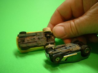
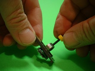
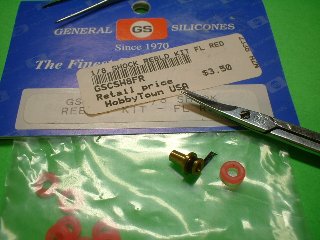
For this project I decided to use a couple old, nasty T-Jets that I picked up for $20 at Tony's Essex show. They are both old solid rivet chassis, which usually works well for me. The photo shows these beauties exactly as they are before
starting. The Hot Rod has a "Pat. Applied for" gear plate and no number on the chassis. The chassis also has little ridges to hold the rear guidepin. The arm is a Christmas Tree of 17.8 ohms. This is a very early chassis, I think! The Dune Buggy has a #8 gear plate and a
#10 chassis. The arm is a green wire of 18 ohms.
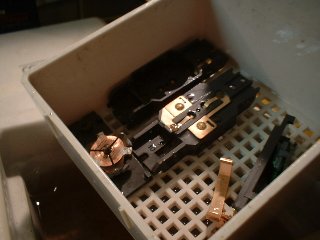
Step one is the disassemble and give them a bath! I'm using a Sonicare jewelry sonic cleaner from Target. The cleaning agent is ammonia based, which I have heard will adversely affect the copper. Simple Green, Pine Sol and other cleaners can also be used.
I ran it for about 15 minutes to clean everything up nicely.
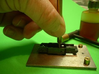
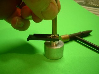
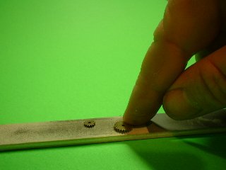
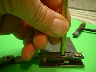
Here we are tightening the rivets after cleaning and drying the chassis. I'm using a tool that is part of the SCM Performance Blue Print kit. Charlie O. from Kansas City makes these kits and they
have all the tools necessary to work on the T-Jet gear train. Email Charlie at scmperformance@kc.rr.com, for availability and prices. Kevin Crowe of Winning Edge also has a new tool for tightening rivets, but he is only selling at shows and not on the web. Probably a tool like a Nail Set found in a lot of normal tool kits would work as well. The whole point is to tighten the plates
so they don't move in racing conditions.
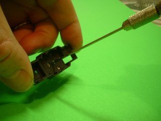
Here we are using an .068 reamer from Wizzard High Performance to open up the armature hole. This is illegal under VHORS rules, although I'm not too convinced they could tell if it was purposefully done...or as a result of normal wear. The object here is to reduce friction.
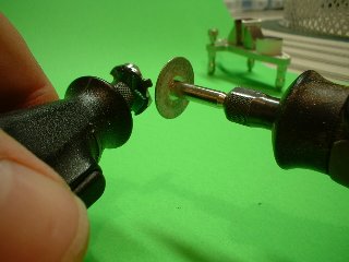
Here I'm using the Winning Edge gear puller to remove the armature pinion.
Here we are using a couple more tools from the SCM Blue Print kit to remove the driven gear and shaft.
I put the gearplate back on the chassis with the clamp holding it, to remove the rails on the gear plate. Using an X-acto blade very carefully do this. I hate doing this and if anyone has a better, safer way let me know! This will also get you in trouble with some rule makers
that only allow gear plate rail removal to lower the body. The Fray rules allow total removal, but you better keep the part that the clamp sits on.
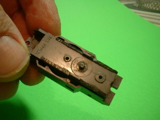
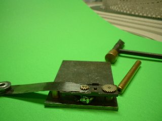
The gear plate with the rails removed, leave the patent number unmolested and don't cut the rail below the plane.
Get some of the foam backed emory boards for fingernail finishing at your local Dollar Tree. I love these things, and they come in three or four different levels of abrasion. Here I'm cleaning up the gears and polishing them.
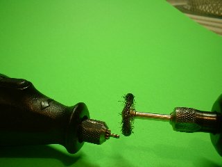
The cluster gear shaft was crudded up badly...yes, it should be replaced, but I wanted to use all the original parts possible for this project. Put the cluster gear shaft in a dremel, and then take another dremel with a wire brush to clean it up.
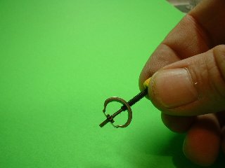
Here we use the gear puller to move the driven pinion gear down the shaft. This will lower friction in the chassis. It's not Fray legal, to cut the cluster gear shaft or to use replacement shafts like JW's titanium ones.
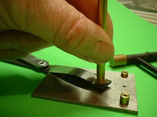
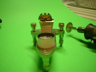
Once again we use the SCM Blue Print kit, now to attach the Driven gear to the cluster gear shaft. I'm using a .005 feeler gauge, with the center cut to go around the shaft. Then just tap it down, the shaft will stick up above the Driven gear, but that is OK.

Here we have the arm chucked in the Minimite Dremel and use another Dremel with the wire brush to clean the crud off of the shaft. A new arm from a NOS Hong Kong chassis, wouldn't have this problem!
Now I'm using my "Poor Man's Lathe" technique to true the stack. One Dremel has a diamond cutting wheel from Harbor Freight. This actually the first time I've tried this, since it's illegal in BeachJet rules. The idea is that you can reduce the air gap by sanding the magnets in Fray Rules.
I'm marking each pole to identify it for balancing...
Balancing is going to be a necessity at the Fray, but this again is not legal for VHORS! Here we have a watch makers poising tool, I found it new on ebay for about $75. The procedure is the same as the razor blade technique, spin the arm and dremel away metal on the heavy side. Balancing can also
be done with epoxy, but it seems to me that adding weight would limit rpm more than removing it. I do have some arms balanced by Ron Hershman with epoxy that work well. I just haven't tried it myself. Alan Galinko and Mike Briggs both do an excellent job balancing T-Jet arms, if you want a pro to do it.
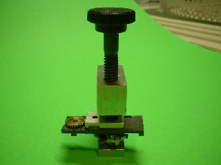
This is JW's press for the armature pinion gear as we put our newly balanced arm back on the gear plate.
Because the press only takes the gear to the top of the armature shaft, now I'm using the SCM Blue Print Kit and my .005 feeler gauge to lower the gear down to .005 thou.
Here and the next picture show the armature shaft sticking proud above the face of the gear.
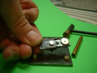
The arm and gear plate are back together, using all the original gears. The arm is balanced and trued, the gear plate rails are cut, the driven pinion repositioned and .005 clearance has been used on both gear assemblies.
Next we want to match up a set of Johnny Lightning magnets. I'm using brp's Magnet Matcher to check through my stock pile of magnets to match them up. This has become not as necessary as when using Aurora magnets, because the
JL magnets are fairly close in strength.
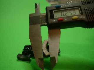
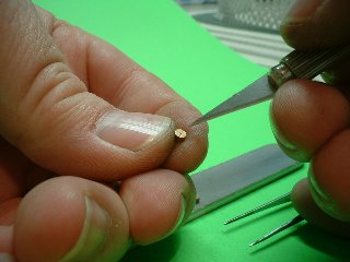
JL magnets are larger than Aurora, and Fray rules allow them to be sanded to fit. VHORS rules only allow sanding on the back side of the magnet, UFHORA rules do not allow any sanding. Certain chassis, especially some of the FlameThrower
chassis accomodate the JL magnets better than others. Watch out for #11 Flame Thrower chassis, they have little ridges in the magnet box, preventing unsanded JL magnets from fitting. Most chassis benefit from sanding the face of the magnet to allow a better fit.
This also reduces the air gap, which can improve performance. Here I'm showing a JL magnet sanded down to .253, which is about the limit that you can do and still meet the Fray rules. The magnet was sanded using the Diamond cutting wheel shown above and the foam emery boards shown above as well. Use you
calipers or check by installing in the chassis so you don't go too far!
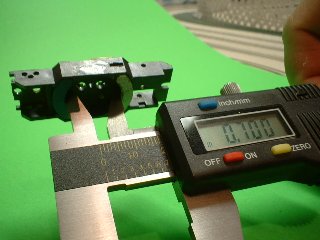
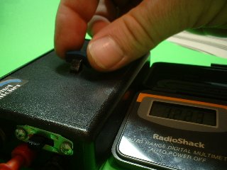
These digital calipers are from Harbor Freight, and go on sale frequently in the 20 some dollar range. This is the Fray limit, .700 between the magnets. They will check this with a plug made by Rick Terry of RT Racing...it's not shown on the website but you can ask for it. Kevin Crowe of Winning Edge also makes
these .700 plugs.
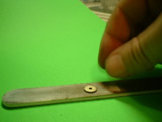
Next we are sanding down the idler gear on the foam board. Be careful in this process, since chamfering the gears are not allowed and too much time sanding on a foam board will chamfer the gears. You just want to polish the gears up, again to remove friction.
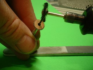
I'm using a wire brush to remove the roughness on the gear teeth. This does the same thing as using a polish like Simichrome and Brasso on the gear train. It's much faster and less messy too!
I'm using Wizzard brushes, because they have been demonstrably faster than any other copper/carbon brush available. Here I'm rubbing them on the fine section of the emery board, just to remove a tiny ridge on the edge of the brush. I've heard tales that this can adversely impact the commutator, if you don't rub it a bit. Never happened to me though...
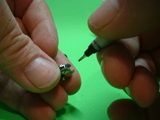
Here we put the "Trek X" on the brush to stop rotation...named for Trek Lawler who spilled the beans about this mod after the 2003 Fray. A single line or x is legal now in the rules.
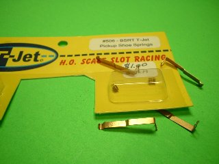
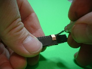
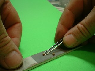
The pickup springs were marginal on the donor chassis, so we are replacing them with BSRT springs. Also I use the BSRT 504 pickup. These are thinner than stock, allowing a lower front end. AML (American Line) shoes also can be used, which because of the square hook design, allows pickup restriction on the hook.
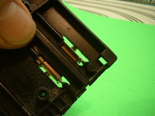
We'll use the BSRT 504 and restrict the pickup travel in front. Take a needle nose pliers and fold the top of the pickup hanger over, towards the front of the car. Just do the very top, otherwise you'll end up with too much restriction...which will prevent clean power pickup. The pickup shoe should be at the level of the bottom of the tire, when extended.
Pickup restriction improves handling by keeping the pickups on the rail and preventing the chassis from rising up.
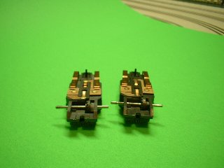
One chassis is being setup for lock and joiner track, the other for the Bowman routed tracks. Both chassis are using brp oversize drill blank axles, that are .0635 in diameter. Drill blanks or reamer blanks are the preferred axle, they improve handling by removing the slop in the rear end. Locktite green or red can be used to glue the crown on to a drill blank axle. These are available through Wizzard or On-Slot. The chassis on the left is using the AFX Specialty crown with two Wizzard plastic spacers,
this gear is still 15 teeth, but smaller in diameter...so smaller tires can be used on the smooth routed tracks. Both chassis are using Aurora guidepins glued in. AML guidepins are legal, but Nu-Rora are not. The Bowman track have a .150" deep slot, just a tad over Lock and Joiner depth.
For front tires, I'm using o-rings from RC car shocks, on Wizzard FR54A brass wheels. To raise the tire height to the Fray mandated minimum size of .300, I'm using a strip of electrical tape under the tire to increase the diameter.
If you like bright colors the rebuild kits for RC Car shocks offer some nice choices. For black o-rings, try most good hardware stores.
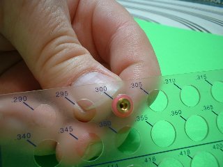
As low as we can go, .300!
Using my Lucky Bobs wheel press, we install .316 Dunlop silicone sponge tires on the chassis for the routed tracks.
Adjust the tires using a puller to get at the 1 5/6" limit.
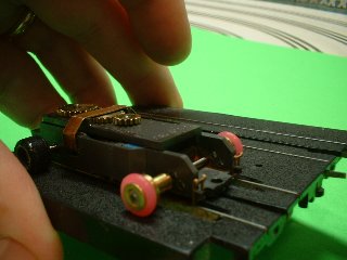
A piece of track, that is cut away under the rail, is used to check for pickup alignment, make sure the contact portion of the pickup lies flat on the rail.
This is the light front end setup, with no spacers. The minimum weight has been upped to 20 grams, so it's possible that you might have to add spacers to meet the weight requirement...if the body is fairly light, like under 2.0 grams.
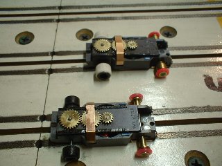
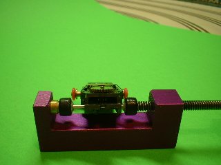
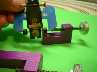
So here we are, ready for the first run after a bit of Thomas H:OyL to lube things up. The chassis in the foreground is for the routed tracks: no spacers on the wheels, small AFX Specialty 15 tooth crown gear, and Dunlop .316 black in the rear. The chassis in the rear is for lock and joiner: features Slottech .350 white silicone sponge rears, Wizzard FR52 heavy spacers
(notched for pickup clearance), stock 15 tooth crown gear. I would break them in for a couple hours on a low voltage power supply, and then try running some laps. The armatures from these cars are probably not going to be fast enough to be raceable, but the setup procedure for the armature is the same for a fast 16 ohm arm. However, that will probably not be legal in Ferndale, because of the cooler temps
at the fairground hall. The method used this year to measure armature resistance, is the total of all three poles has to be over 48 ohms, for an average of 16 per pole. The problem is that arms will measure lower in California...I think it's something to do with having Arnold as the Guv'ner! ;> ...Tom